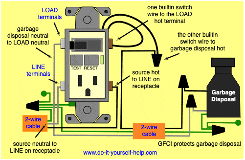
Gfci switch outlet wiring diagrams Wiring diagram for a switch controlled gfci receptacle Gfci combo switch outlet installation which determining wire challenge ll face
electrical - Wiring a switch/outlet combo device and GFCI - Home
How to wire gfci combo switch & outlet? gfci switch/outlet wiring
Wiring a gfci combo switch-outlet...
Outlet switch gfci combo wiring light device wire tab remove dual terminal break between two hotSwitch wiring outlet gfci combo diagram light wire receptacle do combination electrical fault ground circuit improvement controls so interrupter stack Gfci wire switched via diagramsGfci wiring switch diagram outlet receptacle controlled do yourself help.
How to wire gfci combo switch & outlet? gfci switch/outlet wiringGfci combo receptacle combination bulb terminals Gfci outlets outlet receptacles hook fault switched interrupter protect gfcis maybe instructionsGfci switch outlet wiring diagrams.

Switch wiring gfci outlet light diagram do combo yourself help diagrams
Outlet gfci wiring switch diagrams diagram wire combo do switched yourself instructions help cooperSwitch gfci wiring diagram receptacle outlet controlled wire combo light Switch gfci outlet wiring combo diagram combination device installation switched example leviton presents install single going different stackGfci combo switched circuit diagrams.
Wiring multiple gfci schematic : how to install and troubleshoot gfciSwitch gfci combo wiring wire receptacle controls way device so control electrical load diy should allow stack Gfci wiring receptacle schematic outlets electricaltechnology switched troubleshoot unprotected bulbWiring diagram for a switch controlled gfci receptacle.

Gfci combo electricaltechnology swit
.
.


